tonatin3991
Usuario (México)
ESTO A MI ME FUNCIONO PERFECTAMENTE, ME FUNCIONO PARA EL NOKIA5530 Paso 1 ABRIMOS LA CONSOLA (INICIO - EJECUTAR - Y ESCRIBIMOS command)... NOS APARESERA LA CONSOLA DEL MOSO MSDOS.... LO ESCRIBIMOS LO SIGUIENTE: telnet 192.168.1.254 Y LE DAN ENTER Paso 2 NOS APARESERA Username: Y TECLEAMOS Administrator NOS APARESERA Password: Y LO DEJAMOS SIN NADA Y DAMOS EN ENTER... LUEGO NOS APARESERA EL LOGO DE SPEED TOUCH... Y EL LA PARTE DE ABAJO EL NOMBRE DEL ADMINISTRADOR "Administrator" Paso 3 EN administrator ESCRIBIREMOS LO SIGUIENTE: wireless qos config mode=disabled Y ENTER.... ESPERAMOS UN POCO Y NOS SALDRA DE NUEVO Administrator: Paso 4 Y ESCRIBIMOS LO SIGUIENTE: saveall Y DE NUEVO ENTER... SERRAMOS TODO Y LISTOO YA PUEDES CONECTARTE A INTERNET CON TU NOKIA NOTA: EN CASO DE QUE NO PASES DEL PASO 2, POR ALGUN ERROR, REVISA QUE ESTES ESCRIBIENDO BIEN LA PALABRA: Administrator , TAL Y COMO ESTA ESCRITO
Código en PICC para un sistema que encienda una salida digital cuando se presiona un push-button, y al soltarlo permanezca encendido, si se presiona de nuevo el push-button, la salida digital se apagará y permanecerá apagado al soltar el botón. El codigo puedes copiarlo en un nuevo .c compilarlo y funcionara. Si no crea un nuevo proyecto en PICC y pega la seccion a partir de la declaracion de la variable int8 a=0; #include <18F4550.h> #device adc=8 #FUSES NOWDT //No Watch Dog Timer #FUSES WDT128 //Watch Dog Timer uses 1:128 Postscale #FUSES HS //High speed Osc (> 4mhz for PCM/PCH) (>10mhz for PCD) #FUSES NOPROTECT //Code not protected from reading #FUSES NOBROWNOUT //No brownout reset #FUSES BORV20 //Brownout reset at 2.0V #FUSES NOPUT //No Power Up Timer #FUSES NOCPD //No EE protection #FUSES STVREN //Stack full/underflow will cause reset #FUSES NODEBUG //No Debug mode for ICD #FUSES NOLVP //No low voltage prgming, B3(PIC16) or B5(PIC18) used for I/O #FUSES NOWRT //Program memory not write protected #FUSES NOWRTD //Data EEPROM not write protected #FUSES IESO //Internal External Switch Over mode enabled #FUSES FCMEN //Fail-safe clock monitor enabled #FUSES PBADEN //PORTB pins are configured as analog input channels on RESET #FUSES NOWRTC //configuration not registers write protected #FUSES NOWRTB //Boot block not write protected #FUSES NOEBTR //Memory not protected from table reads #FUSES NOEBTRB //Boot block not protected from table reads #FUSES NOCPB //No Boot Block code protection #FUSES MCLR //Master Clear pin enabled #FUSES LPT1OSC //Timer1 configured for low-power operation #FUSES NOXINST //Extended set extension and Indexed Addressing mode disabled (Legacy mode) #FUSES PLL12 //Divide By 12(48MHz oscillator input) #FUSES CPUDIV4 //System Clock by 4 #FUSES USBDIV //USB clock source comes from PLL divide by 2 #FUSES VREGEN //USB voltage regulator enabled #FUSES ICPRT //ICPRT enabled #use delay(clock=20000000) #use rs232(baud=9600,parity=N,xmit=PIN_C6,rcv=PIN_C7,bits=8) int8 a=0; void main() { setup_adc_ports(NO_ANALOGS|VSS_VDD); setup_adc(ADC_CLOCK_DIV_2); setup_psp(PSP_DISABLED); setup_spi(SPI_SS_DISABLED); setup_wdt(WDT_OFF); setup_timer_0(RTCC_INTERNAL); setup_timer_1(T1_DISABLED); setup_timer_2(T2_DISABLED,0,1); setup_timer_3(T3_DISABLED|T3_DIV_BY_1); setup_comparator(NC_NC_NC_NC); setup_vref(FALSE); //Setup_Oscillator parameter not selected from Intr Oscillator Config tab // TODO: USER CODE!! output_low(pin_c0); while (true) { if ((input(pin_a0)==1) & (a==0)) { output_high(pin_c0); a=1; while(input(pin_a0)==1); } if ((input(pin_a0)==1) & (a==1)) { output_low(pin_c0); a=0; while(input(pin_a0)==1); } } } HE AQUI EL CIRCUITO
Para inicar esta informacion obtuve de otra pagina pero la comarto con comunidad. Este es el resultado al termino de los pasos a seguir. Los materiales necesarios para poder aramar una pistola de agua como esta es lo siguiente: Convenientemente, 1 pulgada de PVC encaja muy bien dentro de 1 1/4-pulgada PVC. Estos tamaños de PVC constituyen las secciones de cilindro y pistón de esta pistola de agua. De una longitud de 10 pies (equivalnete a 40 cm aprox) de PVC de cada uno de los tamaños mencionados anteriormente, usted puede hacer cuatro pistolas de agua de 30 pulgadas o seis cañones de 20 pulgadas. Los cañones de 30 pulgadas son los mejores para los niños mayores y adultos, mientras que los cañones de 20 pulgadas son más fáciles para los niños pequeños para manejar. De cualquier manera, el diseño es exactamente la misma. Se puede utilizar un codo de 90 grados para el mango o empuñadura, los empaques para que funcione como una jeringa gigante. dos tipos de tapas. una para el tubo interior y otra para el tubo exterior. Y un tornillo para fijar los empaques. Perforar la tapa exterior y pegarla en el tubo exterior de la pistola. por donde succiona y arroja el chorrro de agua. Lo con la tapa y tubo exterior perforar y pegar. Para esto debemos colocar los empaques en la zona de la perfoacion fijandolos con un tornillo Y en la otra parte del mismo tubo interno colocar el codo de 90 grados que funcionara como mango o empuñadura del arma de agua SALUDOS Y SUERTE CON LA ELABORACION DE ESTE PROYECTO, siganme los buenos y gracias por sus puntuaciones !!!!!
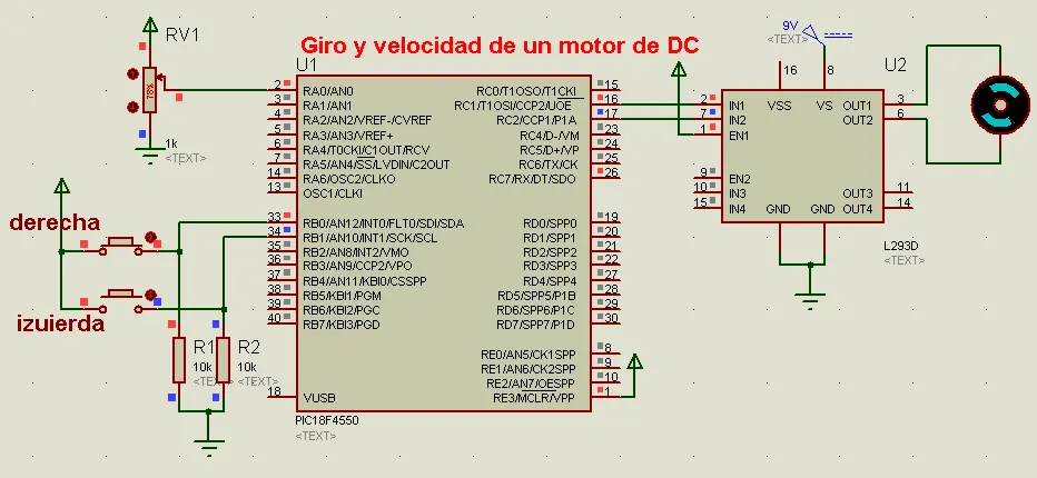
Ssistemadonde mediante dos botones y un potenciómetro (POT) realice el giro ymodificación de velocidad de un motor de DC, con uso de un puente H. He el codigo completo, pueden copiarlo e un .c , si no funciona soo creen un nuevo proyecto desde PICC #include <18F4550.h> #device adc=8 #FUSES NOWDT //No Watch Dog Timer #FUSES WDT128 //Watch Dog Timer uses 1:128 Postscale #FUSES HS //High speed Osc (> 4mhz for PCM/PCH) (>10mhz for PCD) #FUSES NOPROTECT //Code not protected from reading #FUSES NOBROWNOUT //No brownout reset #FUSES BORV20 //Brownout reset at 2.0V #FUSES NOPUT //No Power Up Timer #FUSES NOCPD //No EE protection #FUSES STVREN //Stack full/underflow will cause reset #FUSES NODEBUG //No Debug mode for ICD #FUSES NOLVP //No low voltage prgming, B3(PIC16) or B5(PIC18) used for I/O #FUSES NOWRT //Program memory not write protected #FUSES NOWRTD //Data EEPROM not write protected #FUSES IESO //Internal External Switch Over mode enabled #FUSES FCMEN //Fail-safe clock monitor enabled #FUSES PBADEN //PORTB pins are configured as analog input channels on RESET #FUSES NOWRTC //configuration not registers write protected #FUSES NOWRTB //Boot block not write protected #FUSES NOEBTR //Memory not protected from table reads #FUSES NOEBTRB //Boot block not protected from table reads #FUSES NOCPB //No Boot Block code protection #FUSES MCLR //Master Clear pin enabled #FUSES LPT1OSC //Timer1 configured for low-power operation #FUSES NOXINST //Extended set extension and Indexed Addressing mode disabled (Legacy mode) #FUSES PLL12 //Divide By 12(48MHz oscillator input) #FUSES CPUDIV4 //System Clock by 4 #FUSES USBDIV //USB clock source comes from PLL divide by 2 #FUSES VREGEN //USB voltage regulator enabled #FUSES ICPRT //ICPRT enabled #use delay(clock=20000000) int8 a,b; void main() { setup_adc_ports(AN0|VSS_VDD); setup_adc(ADC_CLOCK_INTERNAL); setup_psp(PSP_DISABLED); setup_spi(SPI_SS_DISABLED); setup_wdt(WDT_OFF); setup_timer_0(RTCC_INTERNAL); setup_timer_1(T1_DISABLED); setup_timer_2(T2_DIV_BY_16,255,1); setup_ccp1(CCP_PWM); setup_ccp2(CCP_PWM); set_pwm1_duty(0); set_pwm2_duty(0); setup_comparator(NC_NC_NC_NC); setup_vref(FALSE); //Setup_Oscillator parameter not selected from Intr Oscillator Config tab // TODO: USER CODE!! while(true){ a=read_adc(); b=input_b();b=b&0x03; if(b==0){ set_pwm1_duty(0); set_pwm2_duty(0); } else if(b==1){ set_pwm1_duty(0); set_pwm2_duty(a); } else if(b==2){ set_pwm1_duty(a); set_pwm2_duty(0); } else if(b==3){ set_pwm1_duty(0); set_pwm2_duty(0); } } } He aqui el circuito
Sistemaque envíe el valor impreso en cada una de las teclas de un teclado matricial auna pantalla de cristal líquido, utilizando un PIC16F4550. He aqui el codigo completo, pueden copiarlo e un .c , si no funciona soo creen un nuevo proyecto desde PICC. #include <18F4550.h> #device adc=8 #FUSES NOWDT //No Watch Dog Timer #FUSES WDT128 //Watch Dog Timer uses 1:128 Postscale #FUSES HS //High speed Osc (> 4mhz for PCM/PCH) (>10mhz for PCD) #FUSES NOPROTECT //Code not protected from reading #FUSES NOBROWNOUT //No brownout reset #FUSES BORV20 //Brownout reset at 2.0V #FUSES NOPUT //No Power Up Timer #FUSES NOCPD //No EE protection #FUSES STVREN //Stack full/underflow will cause reset #FUSES NODEBUG //No Debug mode for ICD #FUSES NOLVP //No low voltage prgming, B3(PIC16) or B5(PIC18) used for I/O #FUSES NOWRT //Program memory not write protected #FUSES NOWRTD //Data EEPROM not write protected #FUSES IESO //Internal External Switch Over mode enabled #FUSES FCMEN //Fail-safe clock monitor enabled #FUSES PBADEN //PORTB pins are configured as analog input channels on RESET #FUSES NOWRTC //configuration not registers write protected #FUSES NOWRTB //Boot block not write protected #FUSES NOEBTR //Memory not protected from table reads #FUSES NOEBTRB //Boot block not protected from table reads #FUSES NOCPB //No Boot Block code protection #FUSES MCLR //Master Clear pin enabled #FUSES LPT1OSC //Timer1 configured for low-power operation #FUSES NOXINST //Extended set extension and Indexed Addressing mode disabled (Legacy mode) #FUSES PLL12 //Divide By 12(48MHz oscillator input) #FUSES CPUDIV4 //System Clock by 4 #FUSES USBDIV //USB clock source comes from PLL divide by 2 #FUSES VREGEN //USB voltage regulator enabled #FUSES ICPRT //ICPRT enabled #use delay(clock=20000000) #include <lcd.c> int secuencia=0x01,aux,a,boton,valor=0; int tecla(){ if(secuencia==0x08) secuencia=0x01; else secuencia=secuencia*2; output_B(secuencia); delay_us(100); //retardo del bit de corrimiento aux=secuencia; if(input(pin_B4)) aux=aux+0x10; else if(input(pin_B5)) aux=aux+0x20; else if(input(pin_B6)) aux=aux+0x40; // else if(input(pin_B7)) //Para un Teclado de 4x4 // aux=aux+0x80; if(aux==secuencia) return 0; else return aux; } char numero(a){ switch(a){ case 0x11:boton='1';break; case 0x21:boton='2';break; case 0x41:boton='3';break; case 0x12:boton='4';break; case 0x22:boton='5';break; case 0x42:boton='6';break; case 0x14:boton='7';break; case 0x24:boton='8';break; case 0x44:boton='9';break; case 0x18:boton='*';break; case 0x28:boton='0';break; case 0x48:boton='#';break; default:boton=' ';break; } return boton; } void main(){ lcd_init(); lcd_gotoxy(1,1);printf(lcd_putc,"fTecla presionada:"; setup_adc_ports(NO_ANALOGS); setup_adc(ADC_OFF); setup_psp(PSP_DISABLED); setup_spi(FALSE); setup_wdt(WDT_OFF); setup_timer_0(RTCC_INTERNAL); setup_timer_1(T1_DISABLED); setup_timer_2(T2_DISABLED,0,1); setup_oscillator(False); while(TRUE){ valor=tecla(); numero(valor); if(valor!=0){ while(tecla()!=0) { // antirrebotes } lcd_gotoxy(2,2);printf(lcd_putc," %c",boton); } } } He aqui el circuito Agradesco tus comentarios, puntos y aportaciones !!!!
Aqui les dejo lo necesario para poder hacer un segudor de linea negra con fondo blanco.... El circuito esta probado por mi ya lo arme.... Lo que dependera d ustedes es como elaboren la estructura del carrito seguidor.... Este es el link en donde esta un video paso a paso que se dvivide en 3 partes que explica como armar el seguidor de linea Parte 1 link: http://www.youtube.com/watch?v=7ogq5OcAx7w Parte 2 link: http://www.youtube.com/watch?v=CaZZ5GPLL98 Parte 3 link: http://www.youtube.com/watch?v=_fsjCsmVrUo NOTA: yo no grabe los videos. NOTA: en caso de que para la parte de los sensores, estes utilizando los CNY70, y no te de una lectura buena, utiliza un circuito de amplificacion para la señal de salida de sensor.