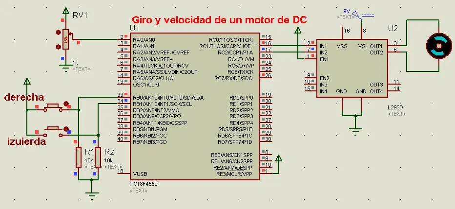
Ssistemadonde mediante dos botones y un potenciómetro (POT) realice el giro ymodificación de velocidad de un motor de DC, con uso de un puente H.
He el codigo completo, pueden copiarlo e un .c , si no funciona soo creen un nuevo proyecto desde PICC
#include <18F4550.h>
#device adc=8
#FUSES NOWDT //No Watch Dog Timer
#FUSES WDT128 //Watch Dog Timer uses 1:128 Postscale
#FUSES HS //High speed Osc (> 4mhz for PCM/PCH) (>10mhz for PCD)
#FUSES NOPROTECT //Code not protected from reading
#FUSES NOBROWNOUT //No brownout reset
#FUSES BORV20 //Brownout reset at 2.0V
#FUSES NOPUT //No Power Up Timer
#FUSES NOCPD //No EE protection
#FUSES STVREN //Stack full/underflow will cause reset
#FUSES NODEBUG //No Debug mode for ICD
#FUSES NOLVP //No low voltage prgming, B3(PIC16) or B5(PIC18) used for I/O
#FUSES NOWRT //Program memory not write protected
#FUSES NOWRTD //Data EEPROM not write protected
#FUSES IESO //Internal External Switch Over mode enabled
#FUSES FCMEN //Fail-safe clock monitor enabled
#FUSES PBADEN //PORTB pins are configured as analog input channels on RESET
#FUSES NOWRTC //configuration not registers write protected
#FUSES NOWRTB //Boot block not write protected
#FUSES NOEBTR //Memory not protected from table reads
#FUSES NOEBTRB //Boot block not protected from table reads
#FUSES NOCPB //No Boot Block code protection
#FUSES MCLR //Master Clear pin enabled
#FUSES LPT1OSC //Timer1 configured for low-power operation
#FUSES NOXINST //Extended set extension and Indexed Addressing mode disabled (Legacy mode)
#FUSES PLL12 //Divide By 12(48MHz oscillator input)
#FUSES CPUDIV4 //System Clock by 4
#FUSES USBDIV //USB clock source comes from PLL divide by 2
#FUSES VREGEN //USB voltage regulator enabled
#FUSES ICPRT //ICPRT enabled
#use delay(clock=20000000)
int8 a,b;
void main()
{
setup_adc_ports(AN0|VSS_VDD);
setup_adc(ADC_CLOCK_INTERNAL);
setup_psp(PSP_DISABLED);
setup_spi(SPI_SS_DISABLED);
setup_wdt(WDT_OFF);
setup_timer_0(RTCC_INTERNAL);
setup_timer_1(T1_DISABLED);
setup_timer_2(T2_DIV_BY_16,255,1);
setup_ccp1(CCP_PWM);
setup_ccp2(CCP_PWM);
set_pwm1_duty(0);
set_pwm2_duty(0);
setup_comparator(NC_NC_NC_NC);
setup_vref(FALSE);
//Setup_Oscillator parameter not selected from Intr Oscillator Config tab
// TODO: USER CODE!!
while(true){
a=read_adc();
b=input_b();b=b&0x03;
if(b==0){
set_pwm1_duty(0);
set_pwm2_duty(0);
}
else if(b==1){
set_pwm1_duty(0);
set_pwm2_duty(a);
}
else if(b==2){
set_pwm1_duty(a);
set_pwm2_duty(0);
}
else if(b==3){
set_pwm1_duty(0);
set_pwm2_duty(0);
}
}
}
He aqui el circuito